
Last week IDX was called to the site at a large commercial residence building in Pretoria, South Africa. Where our client was implementing an IoT solution for remote monitoring and control of various HVAC and power systems in the building. The control system the System Integrator chose in this case was a Modbus-enabled Industrial Micro PC called the Revolution PI.
The client had Modbus sensors connected to boilers, air conditioning systems, ventilation systems and power meters. The Modbus communications between the controller and the sensors were intermittently failing due to various installation and implementation faults:
1. Earthing and Shielding
Within any fieldbus communication installation, one of the requirements to ensure uninterrupted operation is to implement adequate grounding and shielding techniques. Effective grounding and Shielding help to prevent electrostatic and electromagnetic pickup, which can lead to failed communications.
Some of the shielding and grounding requirements for a Modbus RS485 Network:
- Utilising twisted shielded serial cable (120Ω impedance)
- Ensuring continuity of the shield across the entire segment
- Grounding the shield at multiple points (preferably at each device)
- Ensure devices are properly grounded to an appropriate functional earth within cabinets
- Running a potential equalisation cable between cabinets where necessary
The shield surrounding the communication wires will transfer any picked-up noise or interference and drain it to the ground. It is important to ground the shield as you enter and exit cabinets and at each device, this provides the shortest path to ground for any interference picked up on the network.
What we found on-site (Figure 1)
- No continuity of the cable shield
- No grounding of the shield within the cabinets or devices
- No functional earthing of devices within the cabinets
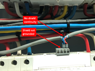
Figure 1: No grounding/shield continuity
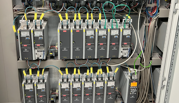
2. Running Modbus cable close to high voltage cabling
High-voltage cables and machinery can interfere with bus communications, they do so by electrostatic and electromagnetic injection. One way to avoid this interference/injection on the bus is to separate your communication cable from the source of interference.
The adequate separation distances between the communication cable (Category 1) and any high-voltage cables/devices (Category 2,3 & 4) are displayed below in Figure 2:
- Category 1: Modbus cable, LAN cables, < 25VAC, < 60VDC
- Category 2: AC: 25V – 400V, DC: 60V – 400V
- Category 3: AC & DC: >400V
- Category 4: Cable at risk from lightning strikes (e.g. cables running between buildings
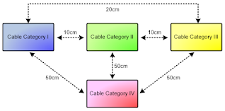
Figure 2: Cable separation diagram
What we found on-site (Figures 3 and 4)
- Running close to 400 VAC cables.
- Severe noise injected on the signal bus
-
Within Figure 4 you can see two scope lines (red and green), this is your B & A lines respectively.
- RS485 is a balanced system and carries the same signal on both lines A & B, however, the exact inverses of each signal on each line. Thus any noise that is picked up should cancel out once the signal is combined.
- This scope was taken on a Modbus installation that was silent and indicates poor implementation of RS485 protection mechanisms.
-
-
Little protection from EMI due to poor earthing and shielding techniques implemented.
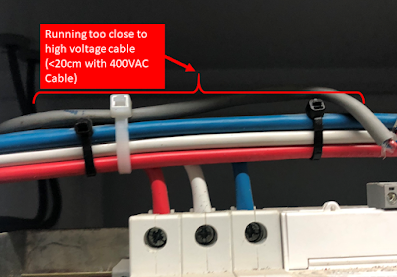
Figure 3: Violation of cable separation requirements
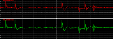
Figure 4: EMI picked up on the Modbus cable due to poor shielding and exposure to high-voltage cables
3. Missing end terminators
Reflections on a fieldbus cable are caused by an impedance mismatch. One of the major contributing factors causing reflections is at the end of the fieldbus line where the signal waveform ‘bounces back’ towards to transmitter and disrupts consecutive signals on the bus (Fig.6).
To prevent these reflections, you can absorb the signal waveform at the end of each line within your Modbus network by installing a 120-ohm resistor at the beginning and end of the segment.
As segment lengths are increased, the effect of reflections without effective terminating resistors installed becomes more severe.
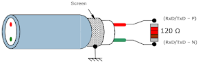
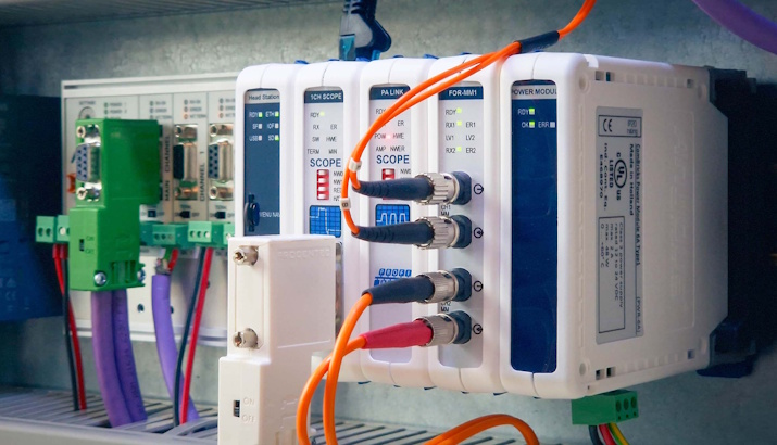
Figure 5: Installed 120Ω resistor and implemented grounded shielding
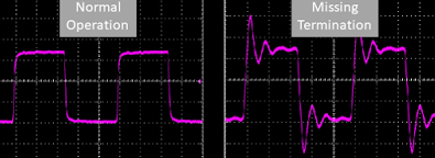
Figure 6: Normal operation (left) vs Missing termination (right) scope image.