Netbiter makes it simple to view your power meter data from a remote location. This week I had the task of setting up a power meter and monitoring this device remotely, via a Netbiter EC350. It was quick and easy to do.
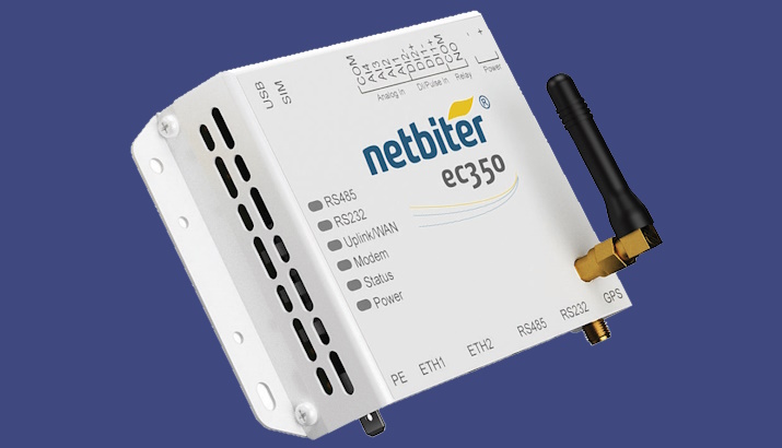
The Netbiter EC350 Gateway shown in Figure 1 is the hardware component of the Netbiter remote monitoring solution. This gateway can connect to a measuring device/field sensor via the following connections: Serial RS232 or RS485, Modbus RTU or TCP, or EtherNet/IP. In my setup, I used RS485, which is what both devices use. Both devices also needed a 24 Vdc power supply as shown in Figure 2 further below.
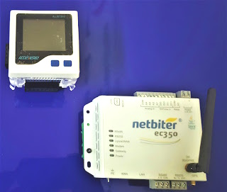
Figure 1: Netbiter EC350 Gateway
The Netbiter uses a cloud service called the Argos to store data that may be remotely accessed later on. The gateway automatically performs data exchange via an Internet-enabled Ethernet connection (WAN) or local cellular networks to the Argos cloud service.
I used the Ethernet port to perform data exchange to the Argos cloud. The method of using cloud service data eliminates the use of public or fixed IP addresses and removes the complexity of VPN tunnelling.
Apart from this, the Argos service also features an authentication login process. The main administrator can grant rights and privileges accordingly to specific user profiles.
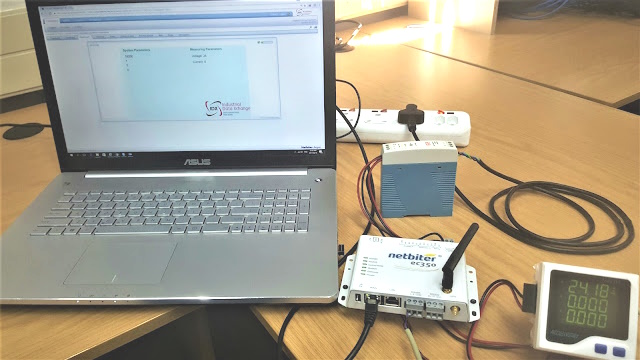
Figure 2: Netbiter EC350 setup with power meter
Steps on connecting the devices:
- Both the Netbiter EC350 and power meter are powered in parallel using the 24V DC power supply. The power supply is powered by 220Vac. Take note of the polarity of the device terminals as DC voltage will not work in the reverse polarity.
- The gateway is then linked via the RS485 com port, to the power meter. Note that the cable needs to be serial-specific, and the connection points (A & B) need to be like for like and not inverted. if multiple devices are used then the com ports will be series to each other.
- The Ethernet cable is connected to the WAN port of the Netbiter and the other end is connected to an Internet-enabled data port.
- Based on the manual – the input terminals may be wired according to their specific measuring point. In my example, I chose to measure voltage which was wired into the available polarity conscious input terminal on the power meter.
Once the wiring was complete, I logged into the Argos profile and added the Modbus registers as parameters in a template. The information needed for adding these registers is found in the power meter’s manual. By using a template, I could install more units and export/import the same template to other various common applications. Eliminating redundant work, and making commissioning easier.
Since the Netbiter EC350 acts as a Modbus Controller in this network, I needed to add the power meter as a device onto the Netbiter EC350 under the configuration tab. In this step, I also specified that the template needs to be allocated to this device.
Now that the device was added, I checked the communication settings (baud rate, parity, etc) and made sure they corresponded to the default of the manual and that the system parameters could be customised to what I need for my network.
After the system checks were done, I downloaded the configuration to the Netbiter and I could browse the device parameters (an option available by the Argos service to present data without configuring a dashboard). Once I saw the data coming through, I compared this to the power meter shown in Figure 2. Since the meter provided a local display, I could verify that my readings were accurate.
Now that the device has been confirmed, I added the parameters to the visualisation tab and created a simple dashboard to present the data in a customised format. I also set up a logging graph and alarm list, to track the behavior of the measured values. I could also extract historical data and reports if needed.
The power meter has functionality to read and write registers, so apart from only reading input values, I could remotely access the writable registers, for example: system parameters like the baud rate or device password can be changed remotely.