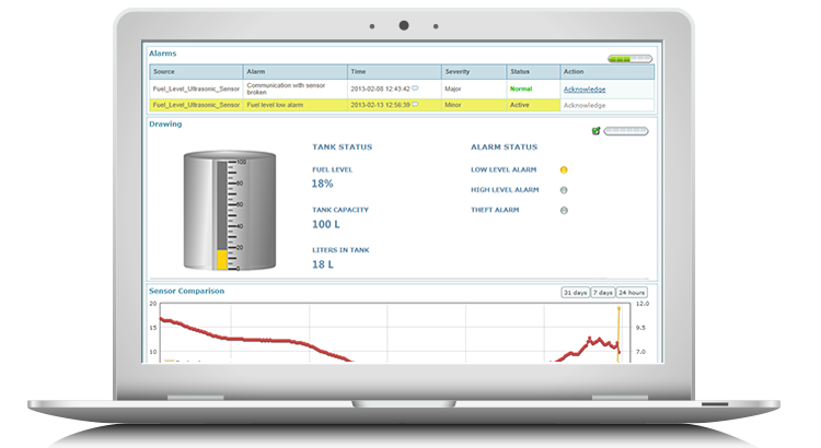
 So, now that we have successfully installed our tank sensor in our last blog: Remotely Monitor Tank Levels Part 1/2, we can move on to the configuration of the Netbiter Argos server (User Interface and logging server for the Netbiter system.
Step 1: Create an account on the Netbiter Argos server
Go to www.netbiter.net and press “create account”. From here you will need to add the particulars supplied with your newly purchased Netbiter Controller including the System ID and the Activation code, this will enable the Argos server to link to your Netbiter and fetch the required information from your devices.
You will also need to supply a unique account name and password (these will form your login details to the server). Lastly, the account creation process will require some personal particulars such as your name and contact details.
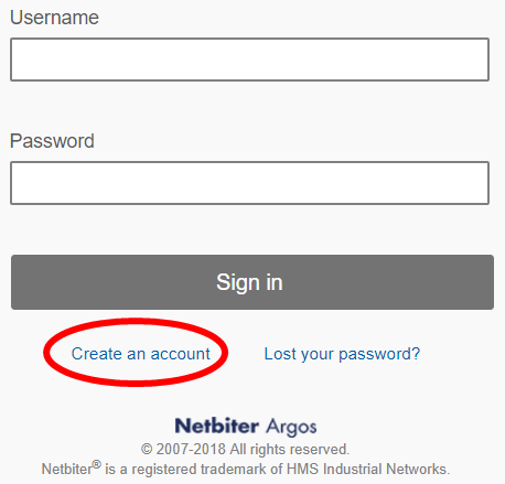
Account will be created once you follow the activation prompts emailed through to you, once you log into your Argos account for the first time, you will see that the Netbiter controller whose details you provided in the previous step is already added to your account and is ready for configuration and parameterisation.
Step 2: Uploading or creating a template for your tank sensor
The Netbiter Argos portal uses “templates” to effectively map the communication information required from your devices, this information could for example be: Modbus Registers, and J1939 engine parameters. Fortunately, there are quite a few pre-built templates readily available for a multitude of generator controllers, UPS systems, Ultrasonic tank sensors and more, you can view and download these templates from the Netbiter website. Uploading a template:
You can upload a template to your account through the following steps:
- Download the relevant template for your device (this is in a .xml format).
- Click on the Management tab, then Templates, and press “Upload” at the bottom of the page.
- Navigate to your .xml template file and press upload.
The template is now available for you to assign to your Netbiter device.
In this case, however, the tank sensor is an integral part of the Netbiter range, and the template should already be available within your Argos account, therefore it is not required that you upload it.
Creating a template:
There may be a case where there is no template available for the device to which you are connected, In this scenario, you will need to create your template. This is a very simple process which can be executed within a couple of steps.
- Ensure that you have the device user manual on hand, which will outlay the device’s communication settings and provide a mapping for the communication registers.
- Whilst logged into your Argos account, Click on the “Management” tab, then the “Templates tab” and press the “Create” button at the bottom of the page.
- Choose the type of template you wish to create (Modbus, SNMP, Ethernet/IP or J1939), this will indicate the communication protocol of the device with which you have connected your Netbiter controller.
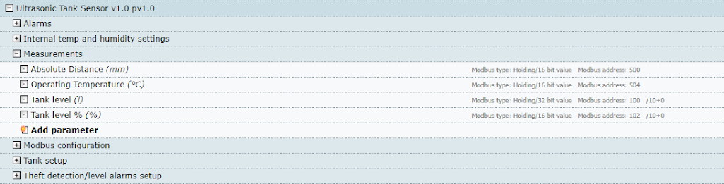
- Choose a name for your template. For example: Ultrasonic Tank Sensor V1.1.
- Either use “Default group” to add in your first parameter, alternatively you can create your own set of groups by pressing “Add group”.
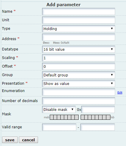
- Create a parameter by pressing “Add parameter”. you will be faced with multiple options in the next screen per parameter, the most important required data is as follows:
6.1) Name – refers to the description of the tag you wish to add within your template. For example, a tag we could name in our fuel sensor configuration could be “Fuel level %”.
6.2) Unit – not required however very useful when it comes to displaying values and reading tags for simplified reading and understanding, in the case of our previously mentioned tag, the unit of interest would be “%”.
6.3) Type – Refers to the register-specific information that will be read by the Netbiter and defines the ‘area’ that the Netbiter controller will read from, as well as how to handle the data received. The data type will be defined within your device user manual and may differ from parameter to parameter. there are four options available (Coil, Discrete input, Holding and input registers).
6.4) Address – Modbus address can be considered similar to that of post boxes, each piece of information requires a unique address where the data can be written to and read from. you will need to take into consideration of the address will need to be offset by 1 or not (ie. addressing starts from 0 or 1).
6.5) Datatype – Within digital communication, there are various data types to convey different pieces of information, this could vary in data size and format (8, 16, 32-bit, floating point, string). Choose the data type declared within the user specifications of your device for the relevant register.
6.6) Scaling – Scaling is to be utilised when the piece of information being read from the device does not represent the true readable value required for the user interface. for example, a temperature sensor may not feedback a Modbus register with the exact temperature read (25.6 DegC), but may only provide the Netbiter with an Analog signal (4-20mA) which is a variation of a small current to represent a value i.e. 4mA represents the lowest temperature value and 20mA the max, any value in between can provide infinite accuracy on a corresponding temperature between the lowest and highest limits.
6.7) Offset – Adds a value to the (scaled) parameter value. For example, a scaled parameter
value of 23.6 DegC plus an offset of 5.0 means that the resulting value will be 23.6 + 5.0 = 28.6 DegC.
***The balance of the required fields can be found in the Argos user manual for advanced action.
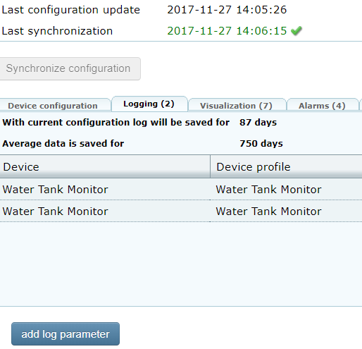
7. Save Press save – the template will now be available to add to your system’s configuration. Remember that any time you make changes to the Netbiters configuration (Modbus, logging, alarm settings etc.) you will need to download the new configuration. This is done within the ‘Management” tab, press ‘Synchronise configuration’ when completing necessary adjustments.
Step 3: Setting up logging parameters, Alarms and communication gateway settings
Setting log points:
The Netbiter can log parameters of interest at varying resolutions. Logging can be useful for trending data points of interest, exporting the data for ERP systems or analysing system usage and potential abuse.
- Within the ‘Management’ tab, open ‘Configuration’ then ‘Logging (0)’.
- Press ‘add log parameter’.
- Select the required Group and Parameter for the data point to be logged.
- Select the required Log interval, this is how often the chosen data point value will be stored, or the resolution of the logged data (ranging from 30 seconds up to 60 minutes).
- Finally, select the Log type:
5.1) Value = the data value will be logged every time at the chosen interval as per point 4.
5.2) Delta = The data point will be logged every time it changes from the previously logged value.
5.3) Hysteres = the data point will be logged every time it changes by a specified amount (Hysteres) from the previously logged value.
6. Press save, don’t forget to press Synchronise configuration for your logging configuration to take effect.
Setting alarms:
The Netbiter has the in-depth alarming capability. This allows you to receive notifications and acknowledge alarms. Alarms are based on a value reaching or exceeding a configured point, on an action e.g. a digital input registering as true. you can assign severity to a certain alarm to determine how that alarm will be handled.
- Within the ‘Management’ tab, open ‘Configuration’ then ‘Alarms (0)’.
- Press ‘add alarm parameter’.
- Select the required Group and Parameter for the alarm to reference.
- Choose necessary alarm variables:
4.1) Trigger =
4.2) Value =
4.3) Severity =
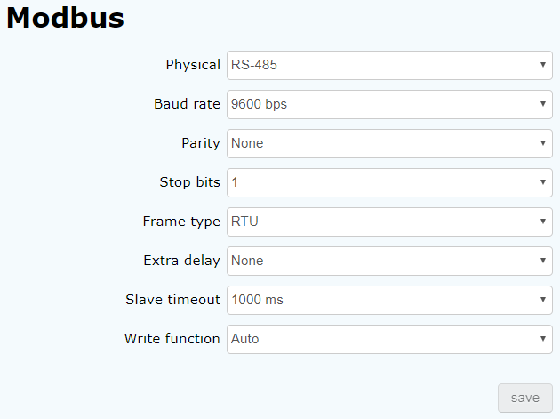
Gateway settings:
Within this tab, you can set up the communication-specific settings (network type, speed, timing and error checking). The relevant communication settings can be sourced from the device user manual, each device connected to the Netbiter needs to conform and support the configured settings. once settings have been entered, press ‘save settings’.
Finally, press Synchronise configuration and test your required inputs to confirm they are being received in good order.